xPlora: Traffic Lights
Introduction
When we travel into a big city or town like Nairobi, we are most likely to meet with thousands of cars moving through the streets and pedestrians cycling or walking along the same streets. To ensure there is order, traffic lights are used to inform people driving, cycling or walking of what to do and what not to do, just as we do in school when we have to wait in line and take turns while the teacher stands there making the children take turns and play nice with each other.
Traffic lights permit orderly movement of people and vehicles to ensure there are no delays. They prevent injuries, fuel wastage and both air and noise pollution.
Traffic lights are made of three lights which are of three different colors to represent each of the messages. These lights are controlled by timers.
What are the different colors that make up traffic lights?
Where else can we use traffic lights?
Things to learn
In this lesson, you will learn about:
- How traffic lights work
- How timers work
- How to build our own traffic lights
How traffic lights work
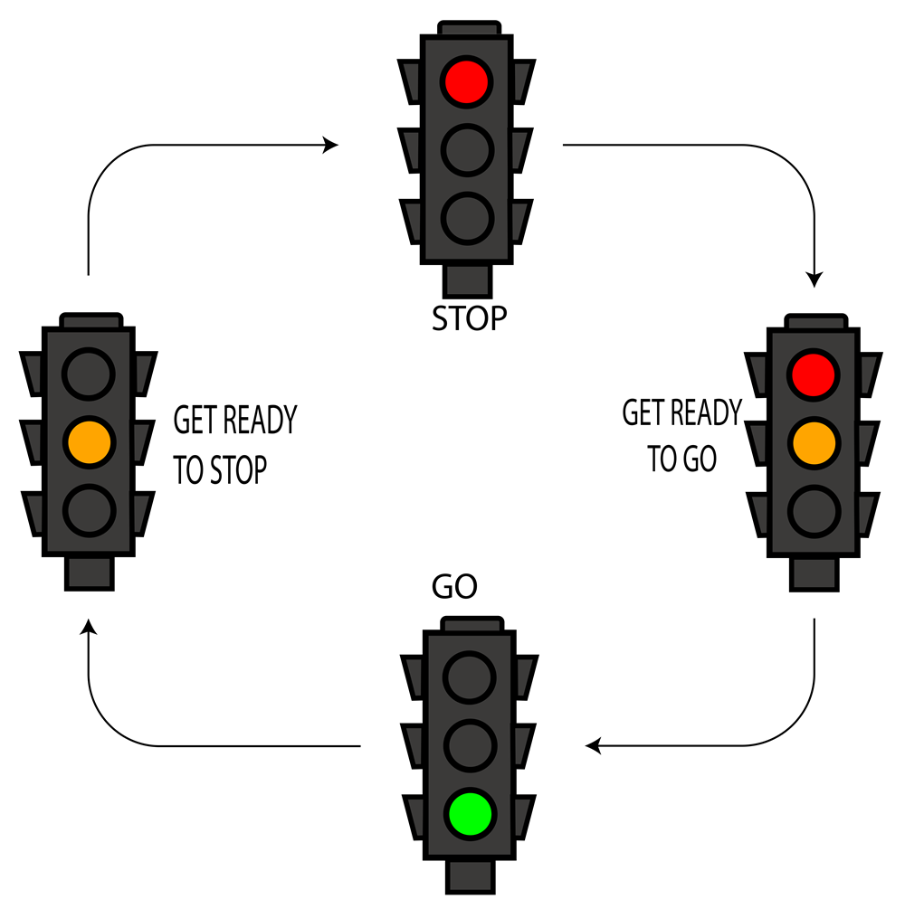
Traffic lights consist of 3 different lights; Red, Orange and Green to give different information.
Whenever we see the red lights, it signals that we should stop where we are. Red and Orange together means we should get ready to go while Green means we should go. Orange alone comes on after Green and signals that we should get ready to stop.
Timing events
Traffic lights uses a timer to change at fixed times or at set intervals.
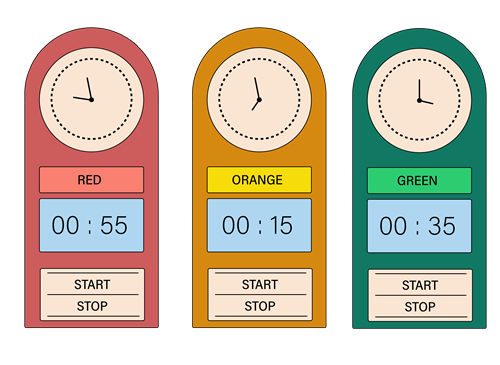
In digital computing a timer is a set of computer instructions that keep track of time and perform certain actions when a specified time period has passed or conditions have been met.
For simple timed events, events that happen one after another, a delayed timer is used.
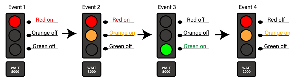
A delay timer pauses the ongoing action for a particular amount of time before it goes to the next.
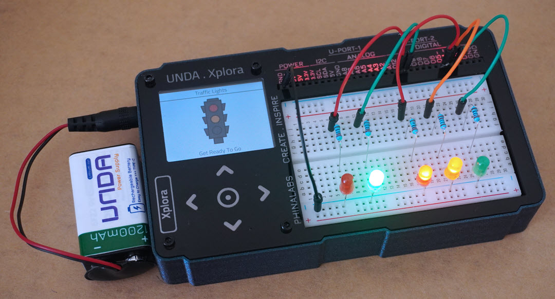
Build the project
In this section we are going to build the traffic lights circuit on the UNDA.Xplora breadboard.
Components
Below are the components used in this project.
| Component | Description |
|---|---|
| 5 x LED |  |
| 5 x resistor (220 ohms) |  |
| 6 x jumper wire |  |
| 1 x battery connector |  |
| 1 x battery |  |
| 1 x Unda Xplora |  |
Step 1
Connecting the first Green LED on the breadboard
- Image
- Video
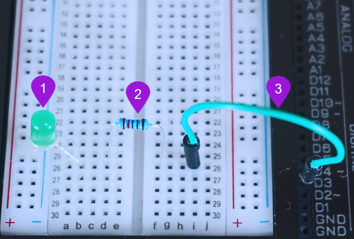
- Placing the first Green LED: Take one green LED from your Unda Xplora kit. Now put the Green LED as shown in the diagram above, with the negative leg (the shorter leg) on the bottom negative terminal and the positive leg (the longer leg) on pin b26 on the breadboard.
- Placing the Resistor: Take one 220 ohm resistor and place it on the breadboard, with one of its leg next to the positive leg of the first Green LED at pin d26 and the other leg placed at pin f26 of the breadboard.
- Connecting a jumper wire: Pick a jumper wire of any color of your choice and connect it from pin D3 to one side of the resistor at pin i26 of the breadboard.
Step 2
Connecting the Orange LED on the breadboard
- Image
- Video
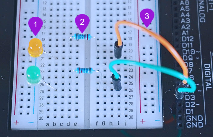
- Placing the LED: Take one Orange LED from your Unda Xplora kit. Now place the Orange LED as shown in the diagram above, with the negative leg (shorter leg) on the bottom negative terminal and the positive leg (the longer leg) on pin b21 on the breadboard.
- Placing the Resistor: Take one 220 ohm resistor and place it on the breadboard, with one of its leg next to the positive leg of the Orange LED at pin d21 and the other leg placed at pin f21 of the breadboard.
- Connecting a jumper wire: Pick a jumper wire of any color of your choice and connect it from pin D4 to one side of the resistor at pin i21 of the breadboard.
Step 3
Connecting the first Red LED on the breadboard
- Image
- Video

- Placing the first RED LED: Take one Red LED from your Unda Xplora kit. Now place the Red LED as shown in the diagram above, with the negative leg (shorter leg) on the bottom negative terminal and the positive leg (the longer leg) on pin b17 on the breadboard.
- Placing the Resistor: Take one 220 ohm resistor and place it on the breadboard, with one of its leg next to the positive leg of the Red LED at pin d17 and the other leg placed at pin f17 of the breadboard.
- Connecting a jumper wire: Pick a jumper wire of any color of your choice and connect it from pin D5 to one side of the resistor at pin i17 of the breadboard.
Step 4
Connecting the second Green LED
- Image
- Video
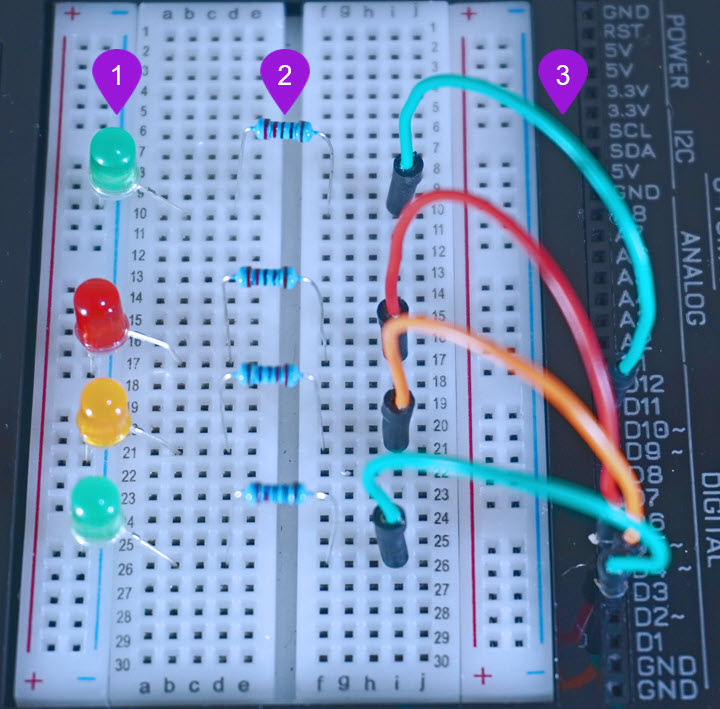
- Placing the second Green LED: Take another green LED from your Unda Xplora kit. Now put the Green LED as shown in the diagram above, with the negative leg (the shorter leg) on the bottom negative terminal and the positive leg (the longer leg) on pin b10 on the breadboard.
- Placing the Resistor: Take one 220 ohm resistor and place it on the breadboard, with one of its leg next to the positive leg of the first Green LED at pin d10 and the other leg placed at pin f10 of the breadboard.
- Connecting a jumper wire: Pick a jumper wire of any color of your choice and connect it from pin D11 to one side of the resistor at pin i10 of the breadboard.
Step 5
Connecting the second Red LED on the breadboard
- Image
- Video
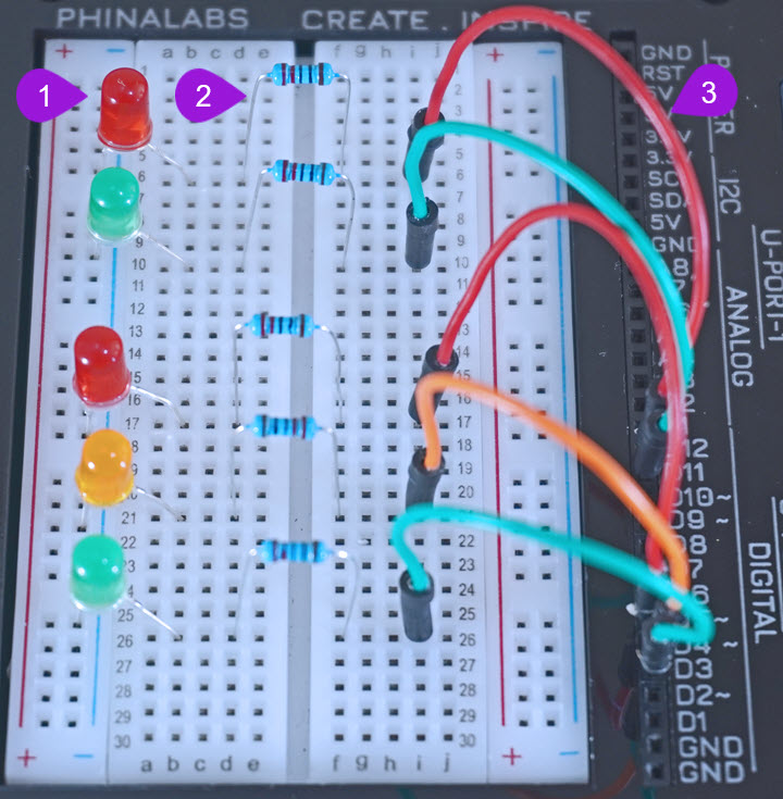
- Placing the second RED LED: Take another Red LED from your Unda Xplora kit. Now place the Red LED as shown in the diagram above, with the negative leg (shorter leg) on the bottom negative terminal and the positive leg (the longer leg) on pin b6 on the breadboard.
- Placing the Resistor: Take one 220 ohm resistor and place it on the breadboard, with one of its leg next to the positive leg of the Red LED at pin d6 and the other leg placed at pin f6 of the breadboard.
- Connecting a jumper wire: Pick a jumper wire of any color of your choice and connect it from pin D12 to one side of the resistor at pin i6 of the breadboard.
Step 6
Connect a jumper wire to ground
- Image
- Video
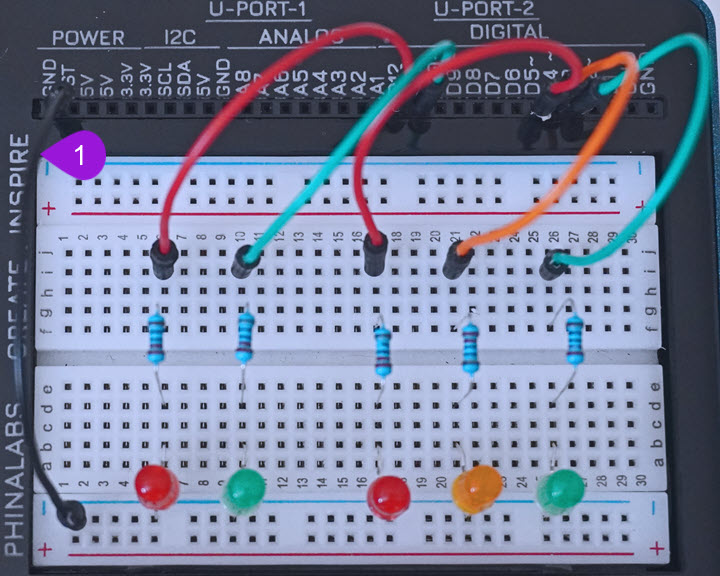
- Pick a jumper wire of your choice. Connect one pin of the jumper wire to the any GND pin of the kit and then connect the other end of the jumper wire to the bottom breadboard negative rail.
Run the Project
Once you are done building the project, connect the battery to the the battery connector and then plug it to the power port of your Unda Xplora to power it on.
Follow the steps below to load up the Traffic Lights Project.
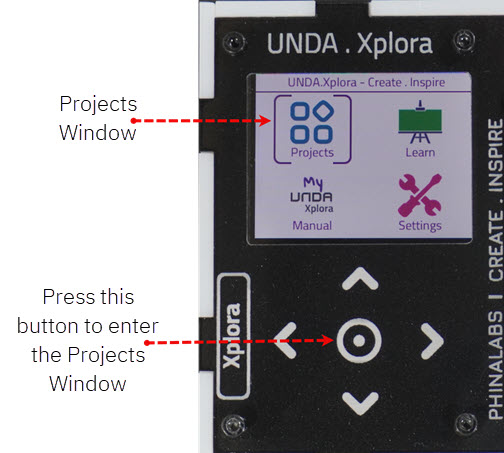
Open Project
From the main window open the projects
Observation
When we run our project, we observe that the LEDs work like traffic lights.
The red LED lights up for 5 seconds to show stop. Both the red and amber then go on for 3 seconds to show that it is time to get ready to go. The green then comes on for 5 seconds showing go! After green, the amber then comes on to show that it is time to get ready to stop before the red comes on again and the process is repeated.