xPlora: Flashing Light
Introduction
Everywhere around us are small but powerful bulbs. In our household appliances, in our phones, in our cars etc. They flash on and off to draw our attention like in an M-Pesa shop advertising, warn us in case of an emergency as a flashing beacon in ambulances, police cars or as decoration during Christmas.
These tiny light bulbs are called LEDs – said as (ell-ee-dees). The word LED stands for “Light Emitting diodes”. LEDs are very bright, require a lot less power, come in many colors and that’s why everyone loves them.
Now that you know about LEDs, can you think of other places where they are used?
Things to learn
In this lesson, you will learn about:
- How LEDs work
- What are Resistors and how they work
- How to automatically turn on and off an LED
LED Lighting
The way that LEDs light work is not that different from how the other bulbs in our homes work. Instead of heating a wire to produce light, a LED is made up of a semiconductor material that gives lots of light when power is passed through.

Polarity is Key
In the electronics rule book, polarity means that electricity can only flow in one direction. An LED has two legs with the long leg as positive, known as anode and short leg as negative, known as cathode. Electricity will flow from the positive to the negative and never the opposite.

Resistors
To prevent the LED from being damaged by excess power, a resistor should be connected. Just as the name, resistors “resist” the flow of electricity and the level depends on the value. The higher the value of the resistor, the more it resists and the less the current will flow.
Resistors have different colored stripes that tell the value of the resistor. The unit of the resistance is called ohm.
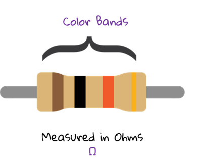
For this lesson we are going to use a 220 Ohms Resistor.
Digital Control
A simple way to switch on or off a lamp is to use a manual switch like in our homes. However we are learning to be digital inventors and in this lesson we are going to learn how to control our lamp automatically to achieve our flashing light goal.
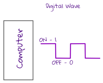
How does digital control works ?
Our computers understand zeros and ones and by sending a command 0 we turn off power and a command 1 we turn on power.
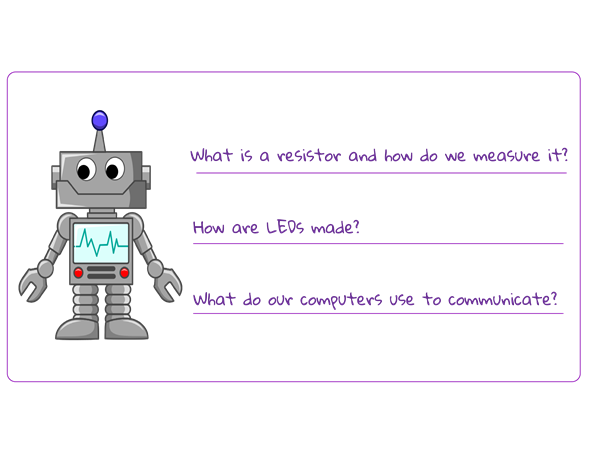
Quiz
Basic Circuit
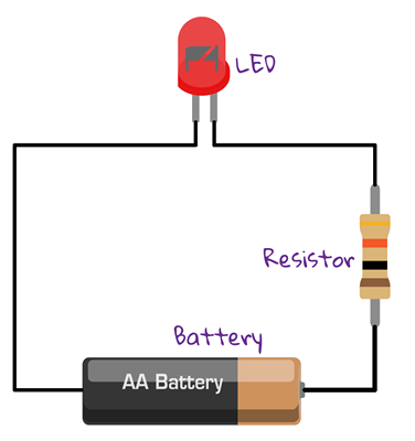
To build a simple LED circuit, we usually connect a battery, resistor and LED as shown in the diagram below.
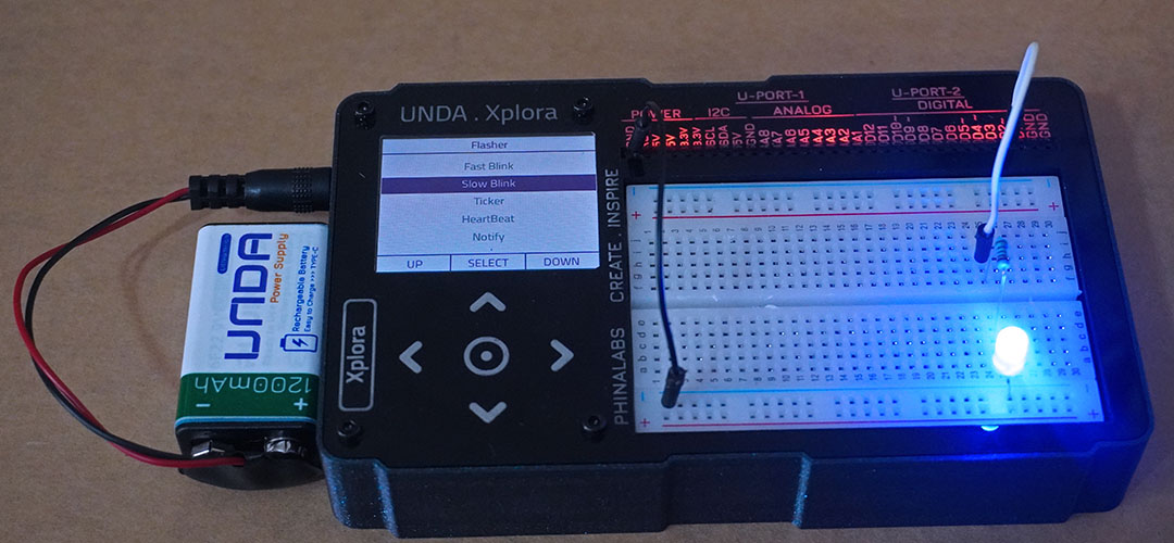
In this project, we will connect the LED to the Unda Xplora digital output port as shown below. The output ports has only two states: ON and OFF that can be thought as HIGH or LOW. When an LED is connected to any of the output ports, the port can only perform two jobs: turning on the LED and turning off the LED.
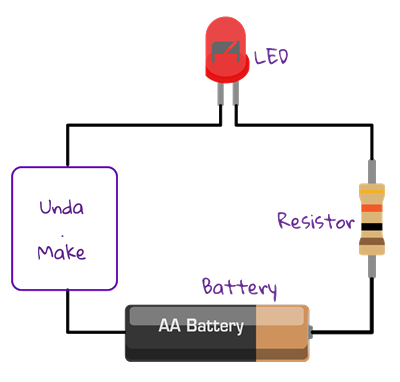
We will connect the LED to digital port, D2
Build the project
In this section we are going to build the flashing light circuit on the UNDA.Xplora breadboard.
Components
Below are the components used in this project.
| Component | Description |
|---|---|
| 1 x LED |  |
| 1 x resistor (220 ohms) |  |
| 2 x jumper wire |  |
| 1 x battery connector |  |
| 1 x battery |  |
| 1 x Unda Xplora |  |
Step 1
Place an LED on the breadboard
- Step
- Build

- Placing the LED on the breadboard: Take an Led from your Unda Xplora kit. The kit has red, blue, yellow, green LEDs. We will use a blue one for this project. Identify the positive leg and the negative leg on the LED. The positive leg is the longer one and the negative leg is the shorter one. Now connect the LED as shown in the diagram above with the negative leg on the bottom negative terminal and positive leg on breadboard pin b25 on the breadboard.
Step 2
Connect a 220 ohm resistor
- Step
- Build

- Connecting a 220 ohm resistor – Take a 220 ohm resistor from the components casing. Connect one end of the resistor from positive leg of the LED at pin c25 on the breadboard. Resistors don’t have positive(+) or negative(-) sides, either side will do. Connect the other side of the resistor across the breadboard to pin f25 as shown above.
Step 3
Connect the jumper wire to digital output
- Step
- Build

- Connecting jumper wire to digital pin D2- Pick a jumper wire of any colour from your Kit. Connect the jumper wire from one end of the resistor at pin h25. Plug the other side of the jumper wire into digital port D2.
Step 4
Connect jumper wire to ground
- Step
- Build

- Connecting jumper wire to GND – Pick another jumper wire, any colour will do. Plug one end of the jumper wire to the ground pin(GND) on the kit. Connect the other end of the jumper wire to any pin on the negative terminal marked with the blue line.
Run the Project
Once you are done building the project, connect the battery to the the battery connector and then plug it to the power port of your Unda Xplora to power it on.
Follow the steps below to load up the Flashing Light Project.
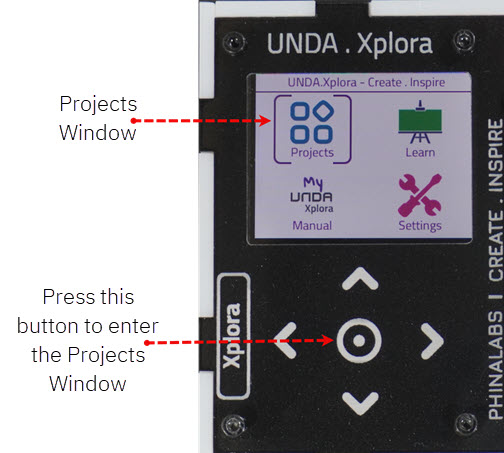
Open Project
From the main window open the projects
Observation
Once the project has uploaded and running, you will observe that LED will flash for half a second, that is 500 milliseconds ON and 500 milliseconds OFF. This will flash repeatedly as long as the power is on
If the LED does not flash, make sure you have connected the circuit correctly.
For the LED to flash ON and OFF, the positive leg of the LED is attached to the digital output pin D2 of our small computer, Unda Xplora. It sends the first instruction to turn the voltage high, turning LED ON and the second instruction to turn the voltage low, turning LED OFF. This instruction is repeated over and over without an end.
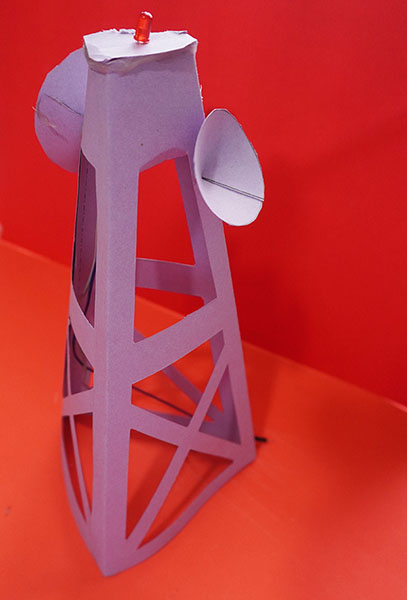
Project: Craft and Play
To have more fun and creativity, we will create a flashing red light on a mobile tower. This red flashing light are used to make the tower more visible to aircrafts and other flying objects preventing accidents and collisions.
Let's get started:
Gather your supplies
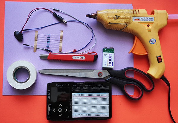
You will need a craft paper or manilla paper, a pair of scissors, a utility knife, two male-female jumper wires, electrical tape and glue. You also need your Unda Xplora and from your components kit an LED, one 220 ohm resistor and two male-male jumper wires. You can get all your supplies at the local supermaket or a bookshop.For glue, a hot glue gun works best, however regular craft glue will also work.
- Always use caution when using a hot glue gun as it can cause serious burns and injuries
- Children should have adult supervison when using hot glue gun and utility knife
- Place some newspaper or disposable material on the surface you are working on to avoid damaging it.
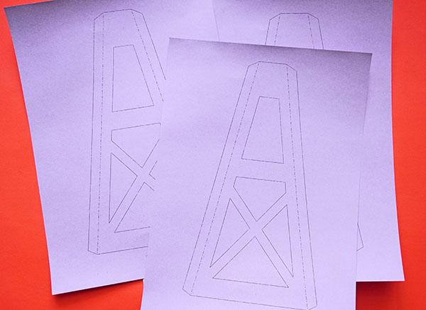
Print out the Mobile tower template
Mobile tower template
Open the printable file above by clicking on this link. Print out three templates on an A4 size. The template makes three sides of the mobile tower.
- To have a durable template, print on a thicker paper like the one used in card making(this is optional)
- You can also draw out the template in case of lack of a printer
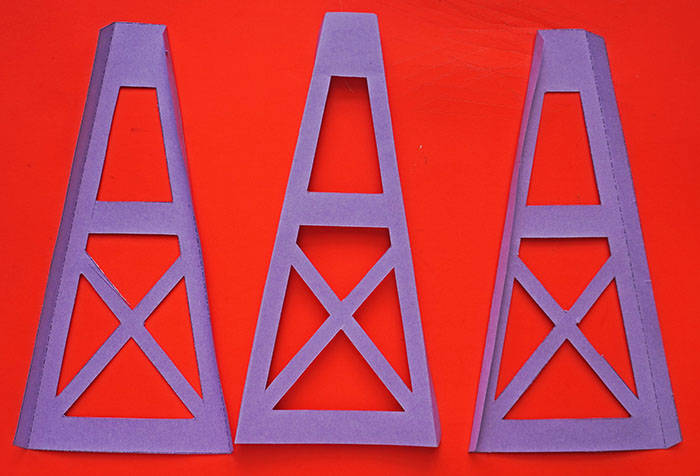
Cut out the mobile tower
Use a pair of scissors to cut along the outer solid lines to remove the outer frame of the mobile tower structure. Proceed to use a utility knife to cut along the solid lines of the inner structure. Carefully remove the cut-out sections to get the full frame of the mobile tower. Once you are done cutting out the structure, fold along the dotted lines of each
- You can also use paint crayons or colour pencils to further decorate your mobile tower
- Be careful when using the pair of scissors to prevent hurting yourself
- Children should have adult supervision when using scissors or a utility knife
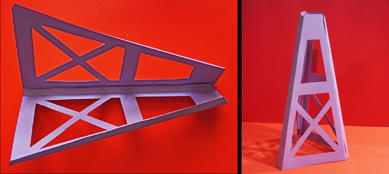
Gluing the mobile tower together
Squeeze a line of glue gently along the inside edge of the wall on each template. Take two sides of the template and glue them together to complete the structure of the mobile tower.
- If you are using glue gun, let it heat up first then squeeze the trigger to release the glue
- Press the glued edges for about 30 seconds to hold
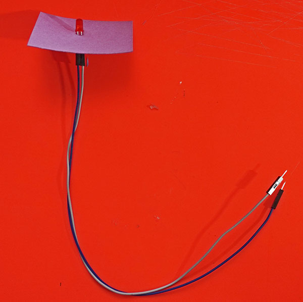
Prepare the LED for installation
Cut out a piece of craft paper and insert the LED legs through it. Attach the male-female jumper wires to the LED legs and secure the connections with electrical tape.
- Don't use glue for the LEDs so that we can reuse the LED in the next projects
- Remember to check the long and the short leg of the LED for positive and negative terminal
- Use different colours of the jumper wires for positive and negative terminal
Completing the mobile tower structure
Trace a circle shape onto the paper you want to use. Locate the centre of the circle by drawing straight lines fom the edges. Cut along one line to the centre and bring the sides of your discs together and glue the sides to form a cone. Glue the cones onto the mobile tower to complete it. Place the LED on top of the structure.
Flashing the mobile tower
Remove the previously used LED from the breadboard and replace it with the LED on the mobile tower. In order to do this:
- Connect the jumper wire that is connected to the tower's LED negative leg to the same position where the negative leg of the LED was originally placed on the breadboard.
- Similarly, connect the jumper wire from the tower's LED positive leg to the position where the positive leg of the LED was initially placed.
Once you are done, Power the board using the battery or using the type-C cable and upload the flashing light project and observe what happens. You can also select the various options on Play section and bserve whta happens.
- How many milliseconds does LED flash on and off
- Next time you spot a mobile tower observe how long it flashes on and off