xPlora: Getting Started
Introduction
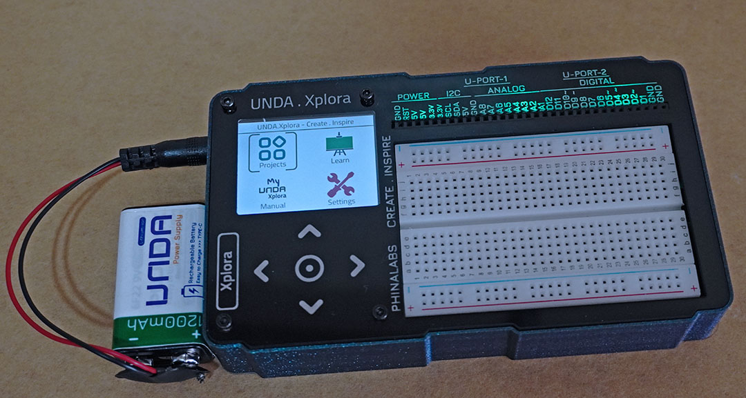
Unda.Xplora is a small portable computer for learning STEM, i.e physical computing and digital electronics.
The kit comes with 20+ inbuilt projects as well the capability to download more projects which are carefully evaluated and designed by our inhouse STEM creative team. The Kit proejcts can hold more than 100 projects therefore creating limitless innnovation and creativity.
The kit also comes with a custom designed components box which makes it eassier to store your components.
Its' built for students, teachers, parents and makers of all ages and the the step by step documentation makes it easier the learning curve easier.
The kit also come with inbuilt manuals, learning content and project build instructions that enables making easier incase a computer or a smartphone is not available.
Overview
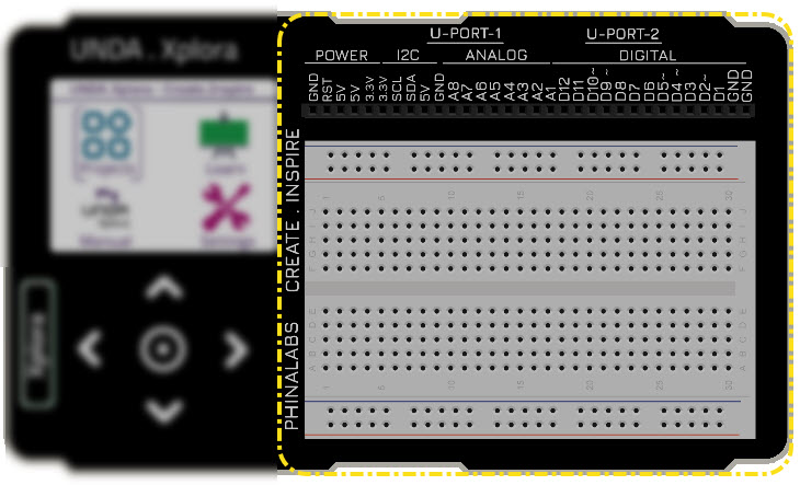
Unda Xplora consists of;
- Main Display
- Touch navigation panel
- Digital Ports
- BreadBoard
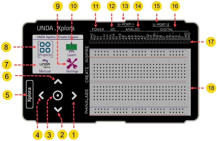
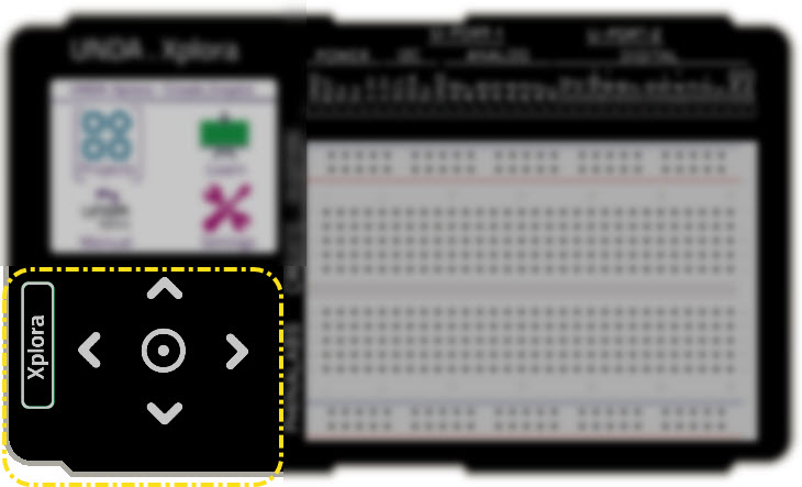
Navigation
| Feature | Image | Type | Description |
|---|---|---|---|
| 1 |  | Left Button | Left Navigation Key |
| 2 |  | Down Button | Down Navigation Key |
| 3 |  | Center Button | Center Navigation Key |
| 4 |  | Right Button | Right Navigation Key |
| 5 |  | Xplora Button | Xplora Navigation Key. Used a Back and home button |
| 6 |  | Up Button | Up Navigation Key. |
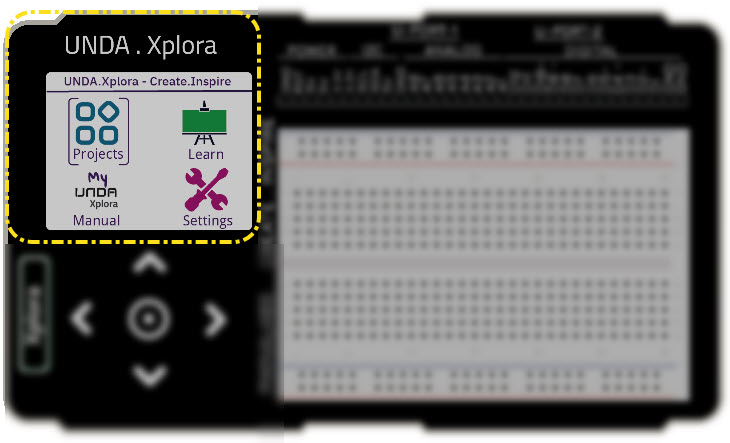
Display
| Feature | Image | Type | Description |
|---|---|---|---|
| 7 |  | Manual | Open inbuilt offline Manual |
| 8 |  | Projects | Open inbuilt Projects |
| 9 |  | Settings | Open Settings; mute sound, change theme color, reset kit etc |
| 10 |  | Learn | Offline extra learning content for digital electronics |
Breadboarding
| Feature | Image | Type | Description |
|---|---|---|---|
| 11 |  | Power Ports | Provide output power supplies for breadboarding; 5V, 3.3V and Ground |
| 12 |  | Communication | Provides a port to connect to external modules and sensors |
| 13 |  | U-Port-1 | A port to connect to Unda.Snap modules |
| 14 |  | Analog Port | Port for connecting analog components e.g variable resistor, temperature sensor etc |
| 15 |  | U-Port-2 | A port to connect to Unda.Snap modules |
| 16 |  | Digital Port | Ports provide digital input and output: D1-D12 are digital in-out ports |
| 17 |  | Breadboarding Port | A Collection of 32 ports; Power, Digital, Analog, and Communication |
| 18 |  | Breadboard | An easy to work platform to make wiring components easier and fun |
Ports
Power and Communication
| Feature | Type | Description |
|---|---|---|
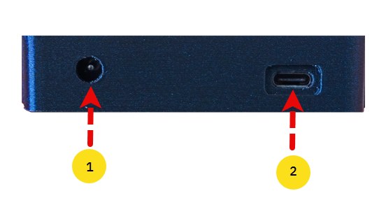
| 1 | Power Jack Connector | This port is used to connect to the battery connector inorder to power on the kit |
| 2 | Firmware Update Port | It is used to connect a USB-B Cable that can be used to update the firmware of the Kit. It also acts as a serial communication port to connect to Scratch. |
Unda.Snap Ports
| Feature | Type | Description |
|---|---|---|
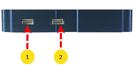
| 1 | U-Port-1 Connector | This port is used to connect to Unda.Snap Modules |
| 2 | U-Port-1 Connector | This port is used to connect to Unda.Snap Modules |
Storage Media Slot
| Feature | Type | Description |
|---|---|---|
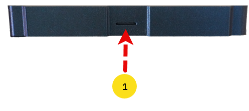
| 1 | Memory Card Slot | This slot can be used to eject the storage media used to store the Kit's data |
Components Casing
The Unda Xplora Kit comes with a components casing that contains basic components, sensors and actuators.
LEDS
Six types of LEDs(Light Emitting Diode) are packed.
- 3 x 5mm different single-Colored LEDs
- 1 x 10mm White-colored LED
- 1 x RGB LED
Green LEDs
Emits green light when powered.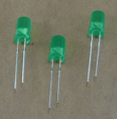
Buttons
Pushbuttons are packed. A pushbutton is a switch that when pressed, it returns to its original position as soon as you release it.
- 1x Green Pushbutton
- 1x Blue Pushbutton
- 1x White Pushbutton
- 1x Black Pushbutton
Green Pushbutton
A pushbutton with a green coloured cap
Sensors
The following sensors are packed:
- 1x Temperature Sensor
- 1x Light Sensor
Temperature Sensor
Senses the ambient temperature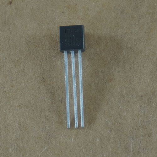
Actuators
Three types of actutators are packed. Actuators are devices that produce motion or action.
- 1x DC Motor
- 1x Servo Motor
- 1x Buzzer
DC Motor
A DC Motor rotates when powered on. A small fan is also attached at the top of the shaft.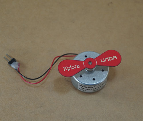
Connecting Wires
Wires are packed with the kit. These wires are used to connect one point or a component to another on the breadboard when building circuits.
- 8x Male-Male Jumper Wires
- 10x Male-Female Jumper Wires
- Assorted Breadboarding Jumper Wires
Male to Male Jumper Wires
These jumper wires are used for connecting components to the breadboarding ports.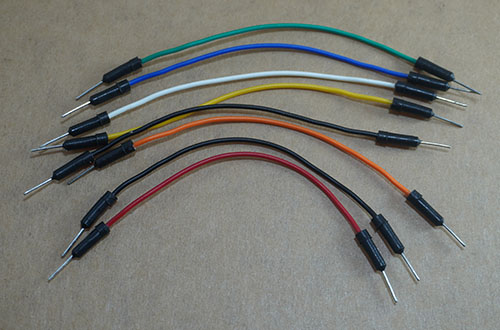
Resistors
Three types of Resistors are packed. The resistors are electronic components that limits current flow.
- 10x 220Ω resistors
- 10x 10KΩ (10 Kilo-ohm) resistors
- 1x Potentiometer (This is a variable resistor)
220Ω Resistor
Provides a resitance of 220 Ohms. It's used to limit current when powering LEDs or other low current components.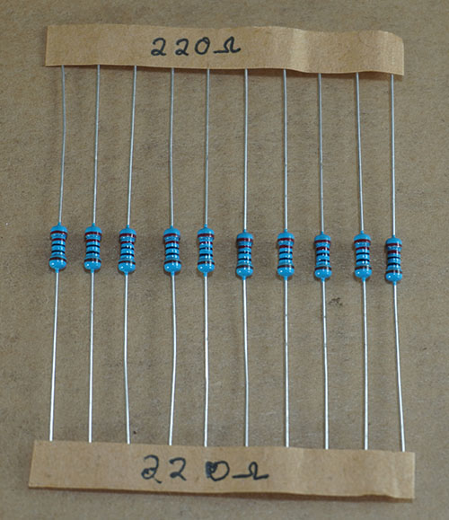
Power
The kit needs to be powered on and this can be achieved using:
- 1x 9V Rechargeable Battery
- 1x Connector for the battery
- 1x USB Cable to charge the battery
Rechargeable Battery
9V Battery to power the kit making it possible to use make your circuits and learn in the absence of mains electricity.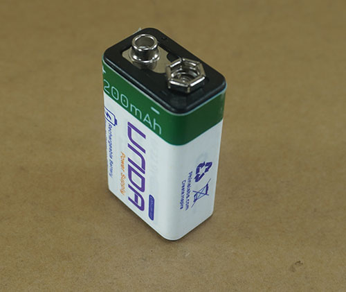
Breadboard Basics
The breadboard is a board with holes called terminal pins that allows a user to build and test circuits without the need of soldering components. The holes allows the user to easily insert electronic components when building circuits.
The breadboard has 4 section:
- 2 X Power Rail Section
- 2 X Circuit Building Section
- 1 X DIP Support
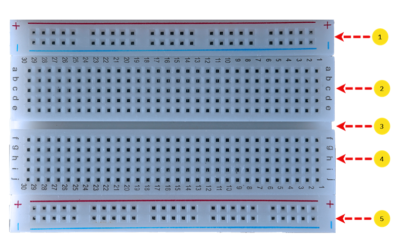
| Feature | Type | Description |
|---|---|---|
| 1 | Top Power Rail Section | This section has a positive terminal marked by red and negative terminal marked by blue color. |
| 2 | Top Circuit Building Section | This section has terminal strips that allow the user to plug in electronic components |
| 3 | DIP Support | This section is a slot running through the breadboard to separate the two circuit building sections of the breadboard |
| 4 | Bottom Circuit Building Section | This section has terminal strips that allow the user to plug in electronic components |
| 5 | Bottom Power Rail Section | This section has a positive terminal marked by red and negative terminal marked by blue color. |
Power Rail Section
As mentioned above the breadboard has two power rail section and they each have a positive terminal rail and a negative terminal rails.
The positive terminal rail is marked with a red colour while the negative terminal is usually indicated using blue colour.
If you want to connect 5v or 3.3V power on the breadbord, you plug one end of the jumper wire to any pin of the positive breaboard rail and the other end of the jumper wire is connected to either any 5V pin or 3.3V pin of the kit.
What does this do?
This means that the breadboard has been supplied with either 5V of power or 3.3V.
The same can be done to connect ground to the breadboard; you plug one end of your jumper wire to any pin of the negative breadboard terminal pin and the other end of the jumper to any GND pin of the kit.
Power Rail Continuity
It is also worth noting that both the positive breadboard rail and negative breadboard rail have horizontal continuity.
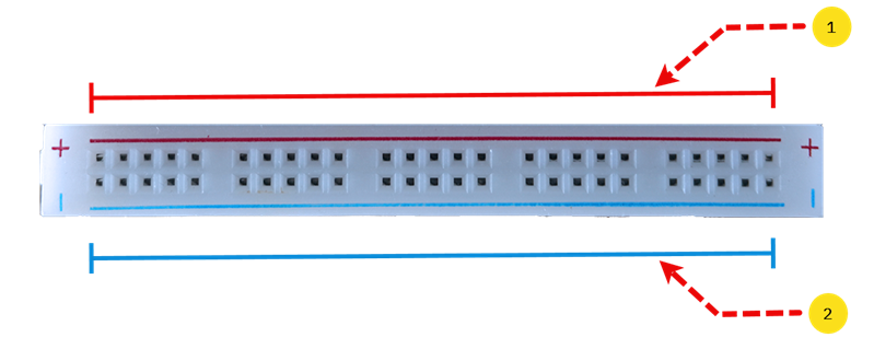
| Feature | Type | Description |
|---|---|---|
| 1 | Positive Breadboard Rail | It has 25 pins that are electrically connected and thus it has horizontal continuity |
| 2 | Negative Breadboard Rail | It has 25 pins that are electrically connected and thus it has horizontal continuity |
What does horizontal continuity mean?
Horizontal continuity means that the pins in each horizontal row of the breadboard are connected to each other. Therefore, when you connect the breadboard's positive rail to either 5V or 3.3V, any pin in that row on the positive rail will be connected to either 5V or 3.3v as well. This also means that you can connect components anywhere along that row and they'll all share the same 5V connection.
The same also applies to any GND connection; When you connect the breadboard's negative rail to Ground (GND), any pin in that row on the negative rail will be connected to GND as well
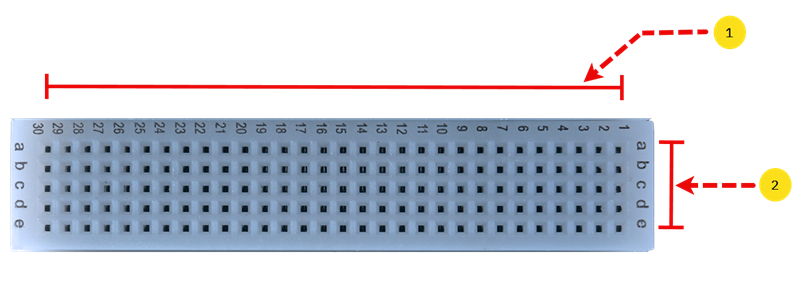
Circuit Building Section
The breadboard comes with two sections used to place components inorder to build and test circuits without the need of soldering. This sections are separated using a groove that is called a DIP Support.
Each section has a total of 150 pins i.e there are 5 rows with 30 pins on each row. The rows and columns are marked differently to make breadboarding easy.
These marking make it easier to connect components on the breadboard and also help you manage and organize your components on the breadboard.
-
The vertical markings represents the columns and they are represented numbers from 1 to 30 which means that verticallyzontally there are 30 columns.
-
The horizontal markings represents the rows and they are represented using letters, with the top section having letters a through to e and the bottom section, letters f through to j. This means that horizontally there 5 rows.
Circuit Building Section Continuity
The circuit build section, has no horizintal continuity but it has there vertical continuity.
| Feature | Type | Description |
|---|---|---|
| 1 | Row Pins | There are 5 rows with each having 30 pins that are not connected to each other and thus there is no horizontal continuity |
| 2 | Column Pins | There are 30 columns with each having 5 pins that are connected to each other and thus there is vertical continuity |
What does vertical continuity mean?
Vertical continuity means that the pins in each vertical column of the breadboard are connected to each other. Therefore when you connect any electronic component to any pin in that column, it will be connected to all the other pins in that same column and they share an electrical connection. Any component connected alomng the column shares the same connections as other components on the column.
However, the circuit building section has no horizontal continuity.
This means that inorder to connect pins in a row for example on row a, pin 30 and pin 29 are not electricaally connected and in order to establish a connection have one has to use breadboarding jumper wires.