xPlora: Timer
Introduction
Are you ready? 30 seconds starts now. Tick, Tock, Tick, Tock!………5 seconds remaining!……three…two…one…times up! There is something just about a countdown. The ticking and knowing that the great BUZZ can erupt any second.
And that’s a timer. A very useful tool for timed activities and independent work. The ticking sounds gets our anxiety up and that’s why we love it. It gets our blood pumping and puts pressure in a good way getting us learning quickly or finishing our work very fast.
A timer gives a visual of the time that has gone by and the time remaining. A perfect tool for test quizzes and games. The first step is to set a time. If an activity is to take 30 seconds, the timer is set to 30 seconds and then the countdown can be started with a push of the start button.
Components
| Component | Description |
|---|---|
| 2 x Pushbutton |  |
| 1 x Buzzer |  |
| 2 x resistor (10 kilo-ohm) |  |
| 5 x jumper wire |  |
| 3 x breadboarding jumper wires |  |
| 1 x battery connector |  |
| 1 x battery |  |
| 1 x Unda Xplora |  |
Step 1
Connecting the Buzzer
- Step
- Build

-
Placing the buzzer on the breadboard: Take the buzzer from the kit. Take note of the positive and negative leg: The positive leg is longer leg and it has been been labelled with a plus sign (+). The negative pin of the buzzer is the leg with the shortest length. Insert the positive leg of the buzzer into pin b23 of the breadboard and insert the negative leg of the buzzer into pin b26 of the breadboard.
-
Connecting the buzzer to digital pin: Using a jumper wire, plug one end of the jumper wire into digital pin D2 and then plug the other end of the wire into pin e23 of the breadboard next to the positive pin of the buzzer.
-
Connecting the buzzer to GND: Using another jumper wire from your kit, plug one pin of the jumper wire into any GNDpin of the UNDA.Xplora. Insert the other pin of the jumper wire into pin e26 of the breadboard next to the negative pin of the buzzer.
Step 2
Connecting the Pushbuttons
- Step
- Build

-
Connecting pushbutton1: Pick one pushbutton of any colour of your choice from the components casing. Connect the pushbutton1 on the breadboard by inserting the two top pins into pin g12 and pin g14. Connect the two bottom pins into pin d12 and pin d14 If the top pins are inserted correctly, then the two bottom pins will easily slot into pin d12 and pin d14.
-
Connecting pushbutton2: Pick another pushbutton of any colour of your choice from the components casing. Connect the pushbutton2 on the breadboard by inserting the two top pins into pin g2 and pin g4. Connect the two bottom pins into pin d2 and pin d4 If the top pins are inserted correctly, then the two bottom pins will easily slot into pin d2 and pin d4.
-
Connecting pushbutton1 to a resistor: Take one 10kilo-ohm resistor from the components provided in your UNDA.Xplora kit. Plug one leg of the resistor into any pin of the bottom negative breadboard rail and then plug the other leg into pin b14 of the breadboard.
-
Connecting pushbutton2 to a resistor: Take another 10kilo-ohm resistor from the components provided in your UNDA.Xplora kit. Plug one leg of the resistor into any pin of the bottom negative breadboard rail and then plug the other leg into pin b4 of the breadboard.
Step 3
Connecting the pushbuttons to power (5V)
- Step
- Build

-
Connecting from 5V Pin: Take one breadboarding jumper from your kit. Insert one of it's leg into any 5V pin of your UNDA.Xplora. Insert the other leg of the into any pin of the top positive breadboard rail. This means that 5V power supplied from the kit will then be supplied to the entire top positive breadbard rail and any components inserted will get 5V of power.
-
Connecting power to pushbutton1: Using another breadboarding jumper wire, connect pushbutton1 to power (5V). This can be done by plugging one end of the breadboarding jumper wire into any pin of the top positive breadboard rail and plugging the other end into pin i12 of the breadboard. Ensure the second end of your conencting wire is correctly inserted into pin i12.
-
Connecting power to pushbutton2: Using another breadboarding jumper wire connect pushbutton2 to power (5V). This can be achieved by plugging one end of the breadboarding jumper wire into any pin of the top positive breadboard rail and plugging the other end into pin i2 of the breadboard. Ensure the second end of your conencting wire is correctly inserted into pin i2.
Step 4
Connecting the pushbuttons to digital pins
- Step
- Build

-
Connecting pushbutton1 to D10: Using a jumper wire from your kit, plug one of the leads of the jumper wire into digital pin D10. Plug the other leg into pin i14 of the breadboard next one of the top pins of the pushbutton1.
-
Connecting pushbutton2 to D11: Using a jumper wire from your kit, plug one of the leads of the jumper wire into digital pin D11. Plug the other leg into pin i4 of the breadboard next one of the top pins of the pushbutton2.
Step 5
Connecting the Ground (GND)
- Step
- Build

- Connecting to GND (Ground): Take another jumper wire from your components casing. Plug one leg into any GND pin of the UNDA.Xplora. Plug the other leg into any pin of te bottom negative breadboard rail.
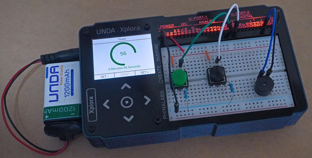
Run the Project
Once you are done building the project, connect the battery to the the battery connector and then plug it to the power port of your Unda Xplora to power it on.
Follow the steps below to load up the Timer Project.
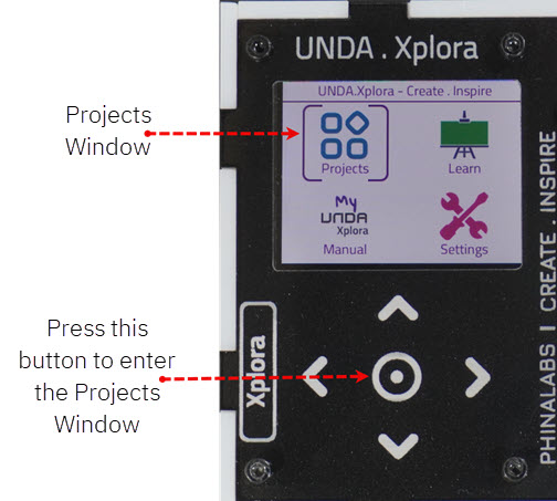
Open Project
From the main window open the projects