xPlora: Notification Lights
Introduction
If you are like most people, you probably pick up a TV remote control at least once or twice a day. Once we pick the remote, we usually press a button to send a message to our TV. On the other hand, a small light on the TV will light up or blinks to let us know that the message has been picked up.
When you want to watch your favorite show, you will first check if the TV is powered on by confirming the presence of a small red light. Next you will use a remote control to turn on the TV, and the light changes to green.
This small light is an RGB LED light known as a notification light. It is located on the lower front of the TV and can display various colours such as blue, green and red to show different states such as power on or power off.
Which other states does your TV show?
Build the project
We will build the Notification Lights Project on the UNDA.Xplora breadboard in this section.
Components
The components needed to build the project are:
| Component | Description |
|---|---|
| 1 x RGB LED |  |
| 3 x resistor (220 ohms) |  |
| 5 x jumper wire |  |
| 1 x pushbutton |  |
| 1 x resistor(10 kilo-ohm) |  |
| 1 x breadboarding jumper wire |  |
| 1 x battery connector |  |
| 1 x battery |  |
| 1 x Unda Xplora |  |
Step 1
Connecting the RGB LED on the breadboard
- Image
- Video
-
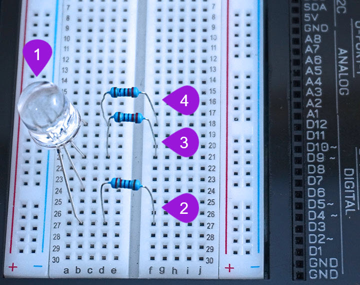
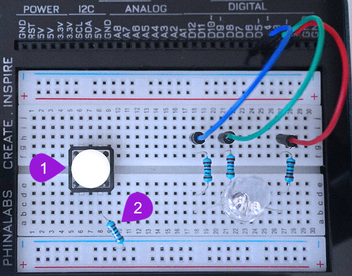
Placing the RGB LED on the breadboard: Take the RGB LED from your components casing kit. Recall that the RGB LED has four pins and that the longest leg of the RGB LED is the negative pin and it is the second pin. Plug the four pins as follows; insert pin one (RED PIN) into pin b27 of the breadboard and then insert the negative pin into pin b24 of the breadboard. Insert the third pin (GREEN PIN) into pin b21 of the breadboard and finally insert the fourth pin (BLUE PIN) into pin b18 of the breadboard.
-
Connecting Resistor 1: Take one 220 ohm resistor from the components casing. Plug one leg of the resistor next to the first pin (the red pin) of the RGB LED at pin d27 of the breadboard. Insert the other leg of the resistor into the breadboard pin f27.
-
Connecting Resistor 2: Take another 220 ohm resistor from the components casing. Plug one leg of the resistor next to the third pin (the green pin) of the RGB LED at pin d21 of the breadboard. Insert the other leg of the resistor into the breadboard pin f21.
-
Connecting Resistor 3: Take a third 220 ohm resistor from the components casing. Plug one leg of the resistor next to the fourth pin (the blue pin) of the RGB LED at pin d18 of the breadboard. Insert the other leg of the resistor into the breadboard pin f18.
Step 2
Connecting the RGB LED pins to digital pins
- Image
- Video
-
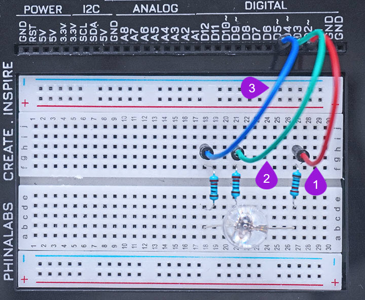
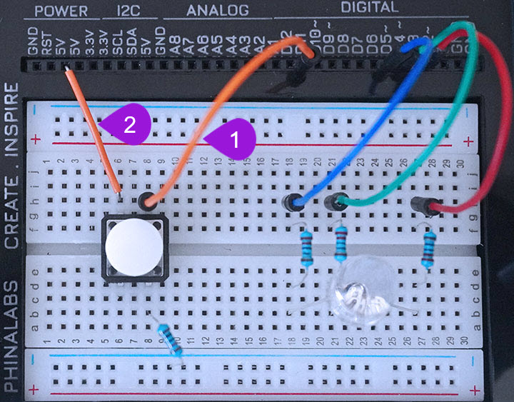
Connecting the first Pin of the RGB LED to D2: Take one jumper wire of any colour of your preference from the kit and insert one leg of the jumper wire into pin D2 of the kit. Insert the other leg of the jumper wire into the breadboard pin h27 next to the first pin of the RGB LED.
-
Connecting the third Pin of the RGB LED to D4: Take another jumper wire with any colour of your preference from the kit and insert one leg of the jumper wire into pin D4 of the kit. Insert the other leg of the jumper wire into the breadboard pin h21 next to the third pin of the RGB LED.
-
Connecting the fourth Pin of the RGB LED to D5: Take a third jumper wire of any colour your preference from the kit and insert one leg of the jumper wire into pin D5 of the kit. Insert the other leg of the jumper wire into the breadboard pin h18 next to the fourth pin of the RGB LED.
Step 3
Connecting the pushbutton on the breadboard
- Image
- Video
-
Connecting the Pushbutton: Take one pushbutton (pick any color of your preference) from the kit. Connect the two top pins of the pushbutton at pins g6 and g8 of the breadboard. Now then connect the other two pins of the pushbutton at pins d6 and d8 of the breadboard.
-
Connecting a 10 Kilo-ohm resistor: Pick one 1o Kilo-ohm resistor from the components casing. Plug one of the resistor's leg into any pin of the bottom breadboard negative rail and the plug the other end into pin b8 next to the bottom leg of the pushbutton.
Step 4
Connecting the pushbutton to power and digital pin 11
- Image
- Video
-
Connecting the pushbutton to D11: Use one jumper wire and then plug one end of the jumper wire into digital pin D11 and then plug the other leg of the jumper wire into pin h8 of the breadboard next to the top pin of the pushbutton.
-
Connecting to power: Using a breadboaridng jumper wire. plu ome leg of the wire into any 5V pin of the UNDA.Xplora. Plug the other end into pin h6 of the brreadboard next to the other top pin of the pushbutton
Step 5
Connecting to GND
- Image
- Video
-
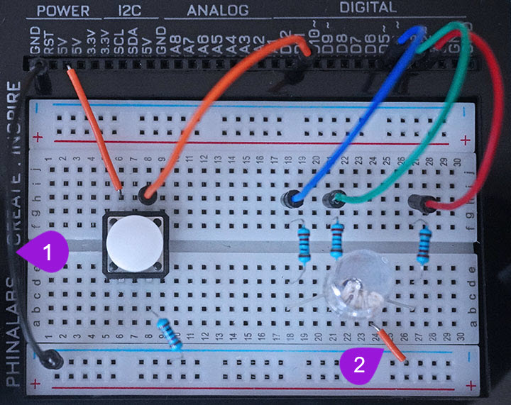
Connecting the GND Pin: Take another jumper wire from the kit and plug one end of the jumper wire into any GND pin of the kit. Plug the other leg of the jumper wire into any pin of the bottom negative breadboard rail (it is marked with a blue-coloured line).
-
Connecting GND to the negative pin of the LED: Take a breadboarding jumper wire (preferably one with a small length) and plug one of it's leads into any negative pin of the bottom breadboard negative rail. Insert the other end of the wire into pin a24 of the breadboard next to the negative pin of the RGB LED.
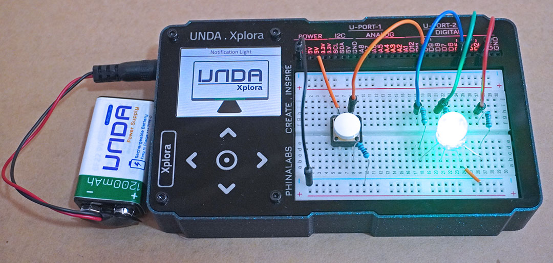
Run the Project
Once you are done building the project, connect the battery to the the battery connector and then plug it to the power port of your Unda Xplora to power it on.
Follow the steps below to load up the Notification Lights Project.
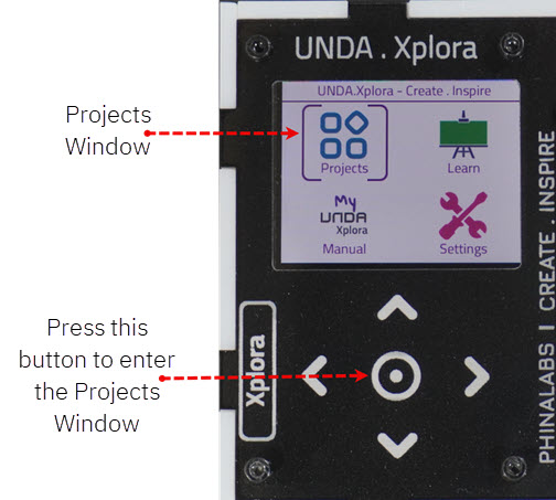
Open Project
From the main window open the projects