xPlora: Colour changing Bulb
Introduction
Have you ever thought of transforming your room using technology? Imagine having the power to change the mood and the feel of your room with just a tap. A colour changing bulb is a great place to get started. With this bulb, you can always change the colour of your room to purple if you want to stimulate your creative juices, green if you want to relax and get cozy, orange if you want to hit the pillow or make your room red just because. And that|\s the magic that a colour changing bulb brings to your room not just making it smarter but more vibrant as well.
At the core of a colour changing bulb is the colour changing LED,known as an RGB led. RGB stands for Red, Green and Blue LED which are the primary colours of light. The RGB LEDs mix these colours to create other different colours for the colour changing bulbs.
Now that you know about colur changing LEDs, where else can they be used?
Things to learn
In this lesson, you will learn about:
- What is an RGB LED
- How RGB LEDs work
- Creating different colours on RGB
About RGB LED
What is RGB?
RGB stands for RED, GREEN and BLUE. RGB is a colour system when mixed or combined can produce different colours. RGB is used to create colours we see on our TV screens, computer monitors and smartphones.
RGB LED
An RGB LED is an LED with three tiny LEDs inside - one RED, one GREEN and one BLUE. By combining these colours, the RGB LED can create different colours. For example, if the RED and GREEN LEDs are on and the BLUE LED is off, the RGB LED will look yellow. This is because RED and GREEN light mix to make yellow.

RGB LED pins
From our previous project, we have seen that an LED has two pins or legs, the positive leg(Anode) and the negative leg(cathode).
However, an RGB LED has four legs rather than two - One for each LED, that is the Red, Green and Blue and the other for the common anode or common cathode
Image of pins of anode and cathode
Types of RGB LEDs
There are two types of RGB LEDs Common Anode and Common Cathode
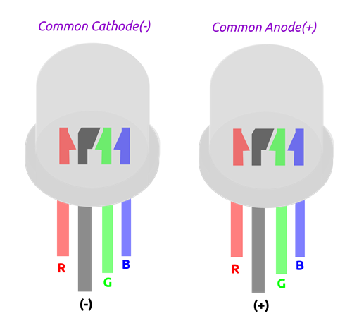
Common anode
In common anode RGB LED, all the three LEDs share the positive connection (anode) as shown
Common cathode
In common cathode RGB LED, three LEDs share the negative connection(cathode) as shown. Image
To control the colours, we connect the red, green and blue pins to the positive terminal of the power supply and the cathode to the negative terminal of the power supply. A resistor is needed for each of the RGB pins.
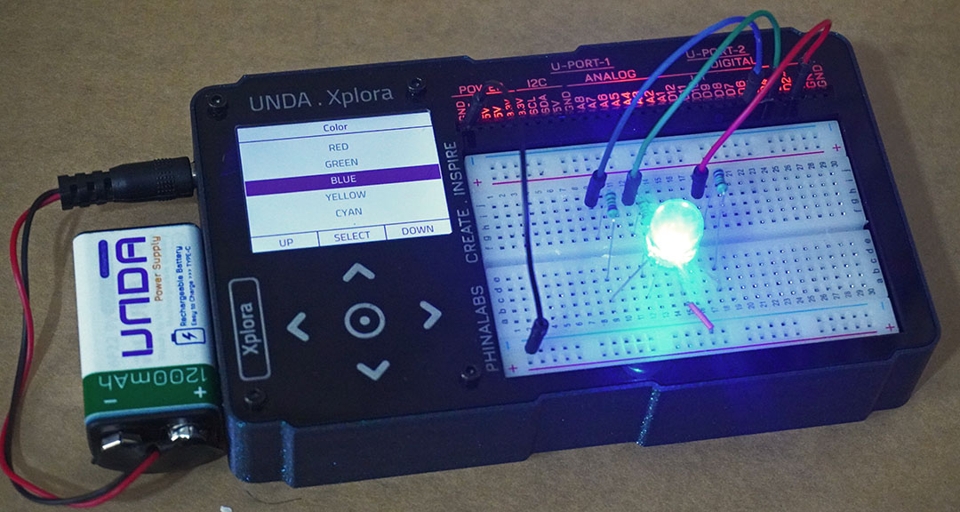
In this project we will use the common cathode RGB LED and a 220 ohm resistor.
How RGB LEDs work
RGB LEDs work by turning the tiny red, green and blue LEDs on and off. The turning ON and OFF allows the creation of various colours just like mixing paint.
To produce a wide range of colours, the three LEDS are combined in various ways. This is done by controlling the LEDs individually by turning them on and off manually or in our case digitally using our microcomputer, Unda Xplora. The turning ON and OFF is done so fast for the human eye to detect.
image
Creating colours on RGB
RGB colours are created by mixing different amounts of light colours. Red, Green and blue are the primary colours of the visible light spectrum. By mixing red, green and blue you produce secondary colours yellow, cyan and magenta
image
Build the project
In this section we are going to build the Colour Changing Bulb circuit on the UNDA.Xplora breadboard.
Components
For this project. you need the following components.
| Component | Description |
|---|---|
| 1 x RGB LED |  |
| 3 x resistor (220 ohms) |  |
| 4 x jumper wire |  |
| 1 x breadboarding jumper wire |  |
| 1 x battery connector |  |
| 1 x battery |  |
| 1 x Unda Xplora |  |
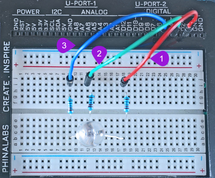
Step 1
Place an RGB LED on the Breadboarding
- Step
- Build
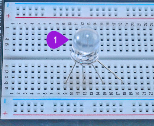
- Placing the RGB LED on the breadboard: Take the RGB LED from your components casing kit. Recall that the RGB LED has four pins and that the longest leg of the RGB LED is the negative pin and it is the second pin. Plug the four pins as follows; insert pin one (RED PIN) into pin b18 of the breadboard and then insert the negative pin into pin b15 of the breadboard. Insert the third pin (GREEN PIN) into pin b12 of the breadboard and finally insert the fourth pin (BLUE PIN) into pin b8 of the breadboard.
Step 2
Connecting 220 ohm resistors
- Step
- Build

-
Connecting Resistor 1: Take one 220 ohm resistor from the components casing. Insert one leg of the resistor next to the first pin (the red) of the RGB LED at pin e18 of the breadboard. Insert the other leg of the resistor into the breadboard pin g18.
-
Connecting Resistor 2: Take the second 220 ohm resistor from the components casing. Insert one leg of the resistor next to the third pin (the green pin) of the RGB LED at pin e12 of the breadboard. Insert the other leg of the resistor into the breadboard pin g12.
-
Connecting Resistor 1: Take the third 220 ohm resistor from the components casing. Insert one leg of the resistor next to the first pin of the RGB LED at pin e9 of the breadboard. Insert the other leg of the resistor into the breadboard pin g9.
Step 3
Connecting the LED pins to Digital Pins
- Step
- Build
-
Connecting the Red Pin to a digital Pin: Take one jumper wire of a any colour of your preference from the kit and insert one leg of the jumper wire into pin D2 of the kit. Insert the other leg of the jumper wire into the breadboard pin i18 next to the first pin of the RGB LED.
-
Connecting the Green Pin to a digital Pin: Take another jumper wire with any colour of your preference from the kit and insert one leg of the jumper wire into pin D4 of the kit. Insert the other leg of the jumper wire into the breadboard pin i12 next to the third pin of the RGB LED.
-
Connecting the Blue Pin to a digital Pin: Take a third jumper wire of any colour your preference from the kit and insert one leg of the jumper wire into pin D6 of the kit. Insert the other leg of the jumper wire into the breadboard pin i9 next to the fourth pin of the RGB LED.
Step 4
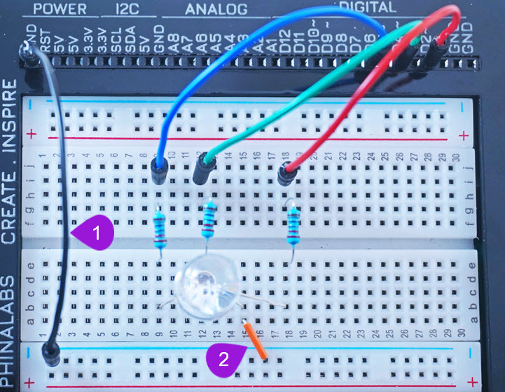
Connecting to Ground Pin
- Step
- Build
-
Connecting to bottom negative breadboard rail: Take one jumper wire of any colour of your preference and plug one end of the jumper wire into any GND pin of the kit. Plug the other end into any pin of the bottom negative breadboard rail.
-
Connecting to negative terminal of the RGB LED: Take one breadboarding jumper wire and plug one end into any pin of the bottom negative breadboard rail. Insert the other end into pin b15 next to the negative leg (the second pin) of the RGB LED
Run the Project
Once you are done building the project, connect the battery to the the battery connector and then plug it to the power port of your Unda Xplora to power it on.
Follow the steps below to load up the Colour Changing Project.
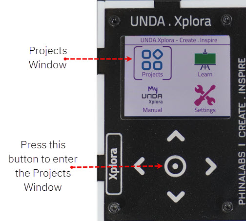
Open Project
From the main window open the projects