xPlora: Volume Control
Introduction
How loud can you turn the music up?
Have you seen the big round knob on a radio or speaker?
That’s the one you twist to turn the sound up, up, UP!
It’s called a volume knob, and it puts you in control. Give it a twist one way and BOOM! the music gets louder and louder, perfect for singing and dancing! Twist it the other way, and the sound gets softer... until it’s calm and quiet.
The volume knob might look small, but it’s a powerful little tool. If you want to sing along? Turn it up! If you need some quiet time? Turn it down.
With just one twist, you can make the sound loud, soft, or anywhere in between.
Ready to build your own volume knob and see what it can do?
Build the project
Let's build the Volume Control Project on the UNDA.Xplora breadboard.
Components
The volume control project can be built using the components below:
| Component | Description |
|---|---|
| 1 x buzzer |  |
| 1 x potentiometer |  |
| 4 x jumper wire |  |
| 2 x breadboarding jumper wire |  |
| 1 x battery connector |  |
| 1 x battery |  |
| 1 x Unda Xplora |  |
Step 1
Placing components on the breadboard
- Step
- Build

1.Connecting the buzzer: Take the buzzer from the components casing kit. Ensure you take note of the positive pin and negative pin of the buzzer. The positive pin is the longer pin and it has been marked with a plus sign and the negative has a shorter leg. Insert the positive pin into pin b21 and insert the negative pin into pin b24 of the breadboard.
2.Connecting the Potentiometer: Take the potentiometer from your components casing. Place the first pin at pin b4 of the breadboard. It is important to know that the three pins are placed at equal distance from each. Therefore, when you place the first one at pin b4, automatically pin two and three will be connected to pin b6 and pin b8 respectively on the breadboard.
Step 2
Connecting the buzzer
- Step
- Build

1.Connecting to digital pin 10: Using a jumper wire, insert one end of the jumper wire into digital pin D10. Insert the other end of the jumper wire into breadboard pin e21 next to the positive pin of the buzzer.
2.Connecting to GND: Using another jumper wire of any color, connect from GND pin on the kit to the breadboard pin e24 next to the negative pin of the buzzer. You can always connect from any GND pin of the kit as long as the other end of the jumper wire is connected next to the negative pin of the buzzer.
Step 3
Connecting the Potentiometer
- Step
- Build

1.Connecting to the negative breadboard rail: Take one breadboarding jumper wire from the components casing kit (a smaller sized one will make conection easier). Connect one end of the breadboarding jumper wire to any GND pin on the kit and connect the other end to the top negative breadboard rail. You can connect to any GND pin as long as it has not already been connected to any component on the breadboard.
2.Connecting to the negative pin of the potentiometer: Using a breadboarding jumper wire (it is recommended to use a larger sized breadboarding wire), connect one end to any pin of the top negative breadboard rail and the other end of the jumper wire to breadboard pin e8 next to the third pin of the potentiometer as shown above. The third pin in this case will be the negative pin of the potentiometer.
3.Connecting to the signal pin of the potentiometer: Using a jumper wire (use any color of your choice), connect one end of the jumper wire to analog pin A3 and the other end of the jumper wire to breadboard pin e6 next to the second pin of the potentiometer as shown above. The second pin is the signal pin of the potentiometer.
4.Connecting to the positive pin of the potentiometer: Using another jumper wire of any color, connect from any 5V pin of the kit to the breadboard pin e4 next to the first pin of the potentiometer as shown above. The first pin will be the the positive pin of the potentiometer which is connected to power, in this our case power of 5V.
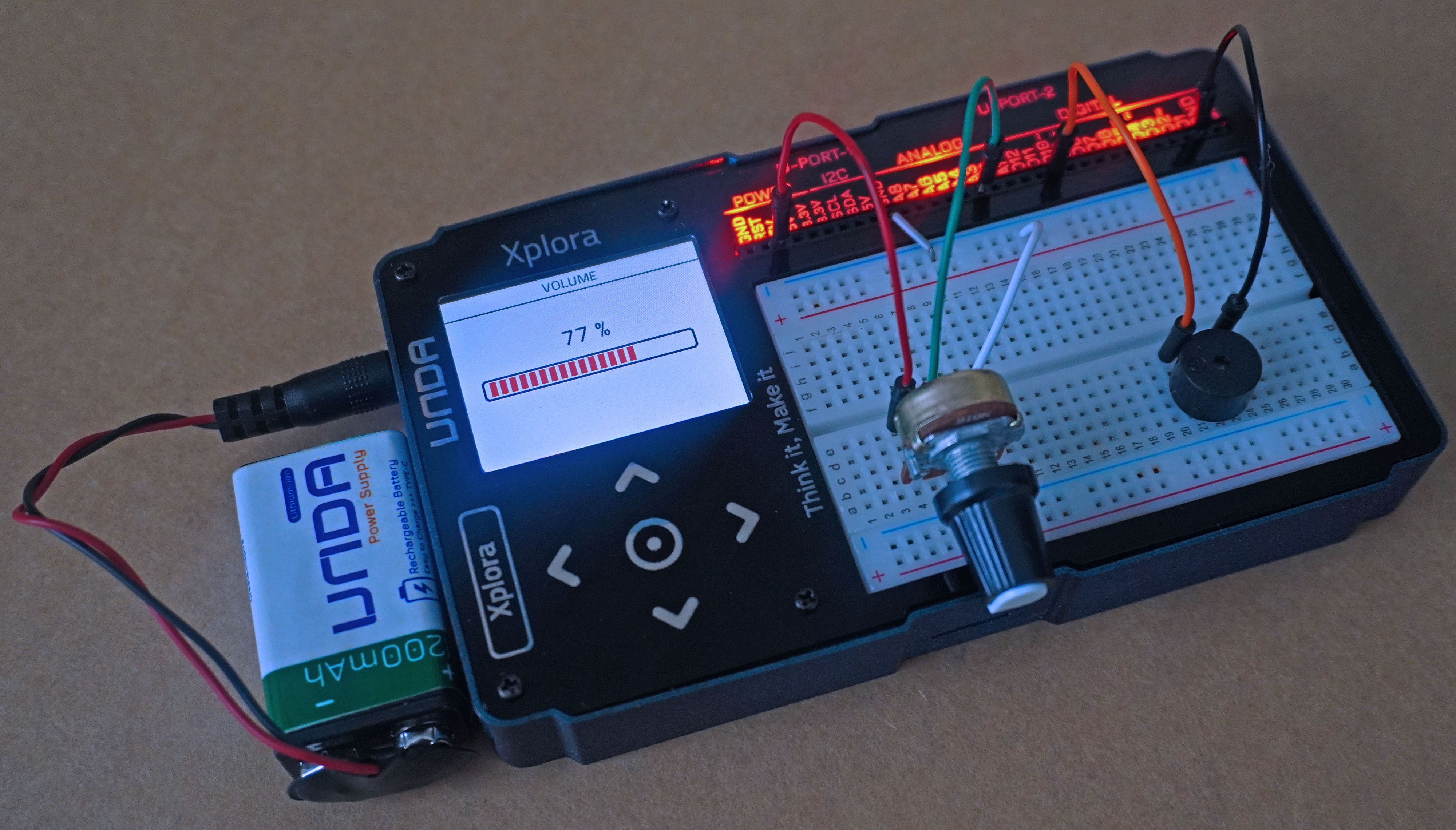
Run the Project
Once you are done with building the project, connect the battery to the the battery connector and then plug it to the power port of your Unda Xplora to power it on.
Follow the steps below to load up the Volume Control Project.
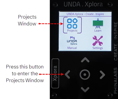
Open Project
From the main window open the projects