xPlora: Dashboard
Introduction
Build the project
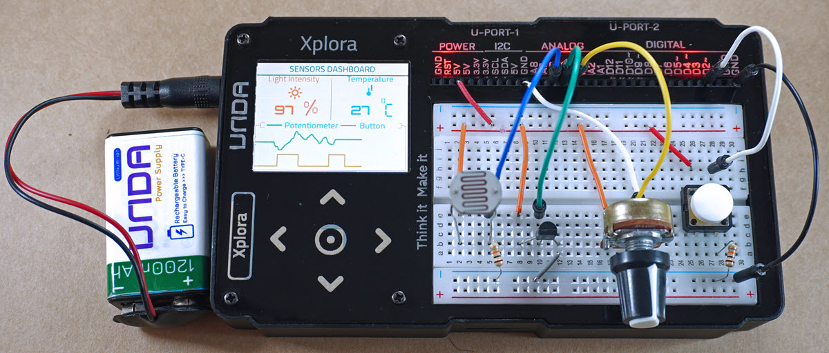
In this section we will explore how to build a sensor dashboard.
Components
To build the project you will need:
| Component | Description |
|---|---|
| 1 x Light Sensor | 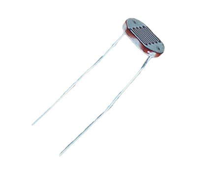 |
| 1 x Temperature Sensor | 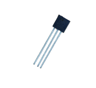 |
| 1 x potentiometer | 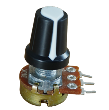 |
| 1 x pushbutton | 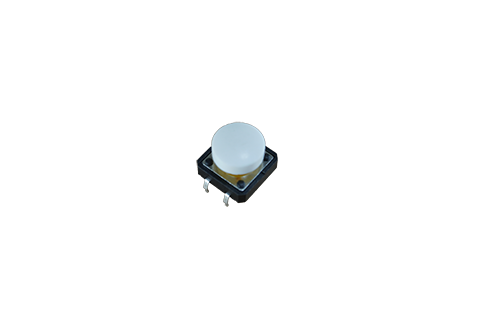 |
| 2 x resistor (10Kilo-Ohm) | 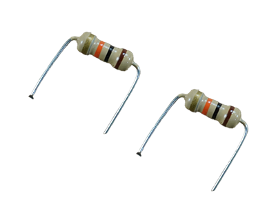 |
| 5 x jumper wire | 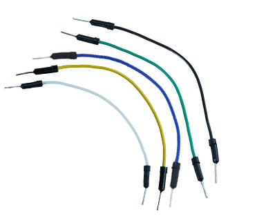 |
| 7 x breadboarding jumper wire | 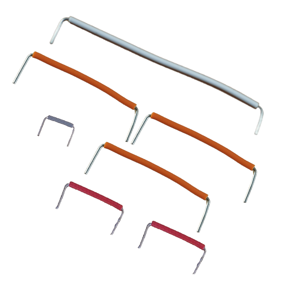 |
| 1 x battery connector | 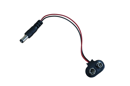 |
| 1 x battery | 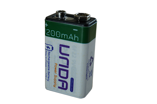 |
| 1 x Unda Xplora | 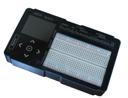 |
Step 1
Connecting the components on the breadboard
- Step
- Build
-
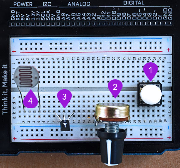
Connecting the pushbutton: Pick one pushbutton of any colour of your choice from the components casing. Connect the pushbutton1 on the breadboard by inserting the two top pins into pin c28 and pin c26. Connect the two bottom pins into pin f28 and pin f26 If the top pins are inserted correctly, then the two bottom pins will easily slot into pin f28 and pin f26.
-
Connecting the Potentiometer: Take the potentiometer from the Tinker Box components casing. Place the first pin at pin b17 of the breadboard. It is important to know that the three pins are placed at equal distance from each. Therefore, when you place the first one at pin b17, automatically pin two and three will be connected to pin b19 and pin b21 respectively on the breadboard.
-
Connecting the temperature sensor: Take the temperature sensor from the components kit. Connect it with the flat side facing you and bulgy side facing away from you. Connect the positive pin , which is pin 1 of the sensor into breadbord pin b8. Proceed to insert the second pin(signal pin) into breadboard pin b10 and the third pin which is the negative pin of the sensor into breadboard pin b12.
-
Connecting the Light Sensor: Pick the Light Sensor from the components casing. The light sensor has two legs and it also has no polarity and thus you can connect it in any orientation. Insert the one of its' legs into breadboard pin b2 and then plug the other leg of the light sensor into breadboard pin b5.
Step 2
Connecting resistors on the breadboard
- Step
- Build
-
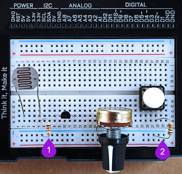
Connecting the light sensor to a resistor: Pick a 10K (10 Kilo-ohm) resistor from the components casing. Insert one of the ends of the resistor into any pin on the bottom negative breadboard rail. Plug the other end into breadoard pin a5 next to one of the legs of the light sensor.
-
Connecting the pushbutton to a resistor: Pick another 10K (10 Kilo-ohm) resistor from the components casing. Insert one of the ends of the resistor into any pin on the bottom negative breadboard rail. Plug the other end into breadoard pin a28 next to one of the legs of the light sensor.
Step 3
Connecting the components to power(5V)
- Step
- Build
-
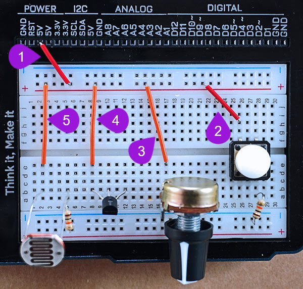
Connecting to breadboard positive rail: Using one breadboarding jumper wire, connect from any 5V pin of the kit to the top positive breadboard rail .
-
Connecting to pushbutton: Take another breadboarding jumper wire and connect from the top positive breadboard rail to one pin of the pushbutton at pin h26 of the breadboard. Remember that you can connect from any pin of the positive breadboard rail as long as the other pin of the breadboarding jumper wire is connected to pin h26 of the breadboard.
-
Connecting to potentiometer: Take another breadboarding jumper wire and connect from the top positive breadboard rail to the first pin of the potentiometer at pin e17 of the breadboard.
-
Connecting to temperature Sensor: Using another breadboarding jumper wire, connect from any pin of the top positive breadboard rail to breadboard pin e8 next to the first pin (positive pin) of the temperature sensor.
-
Connecting to light sensor: With a fifth breadboarding jumper wire, conect from any pin of the top positive breadboard rail to breadboard pin e2 next to the first pin of the light sensor.
Step 4
Connecting the circuit to Ground
- Step
- Build
-
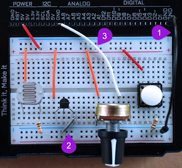
Connecting from GND: Using a jumper wire, insert one end of the wire into any GND of your UNDA.Xplora. Insert the other end of the jumper wire into ** any pin** on the bottom negative breadboard rail.
-
Connecting to the negative pin of the temperature sensor: Using a breadboarding jumper wire, connect one end to any pin of the bottom negative breadboard rail and the other end of the jumper wire to breadboard pin a12 next to the third pin of the temperature sensor (negative pin) as shown above. The third pin in this case will be the negative pin of the potentiometer.
-
Connecting to the negative pin of the potentiometer: Using a breadboarding jumper wire (it is recommended to use a larger sized breadboarding wire), connect one end to any pin of the bottom negative breadboard rail and the other end of the jumper wire to breadboard pin e21 next to the third pin of the potentiometer as shown above. The third pin in this case will be the negative pin of the potentiometer.
Step 5
Connecting the signal pins of the components
- Step
- Build
-
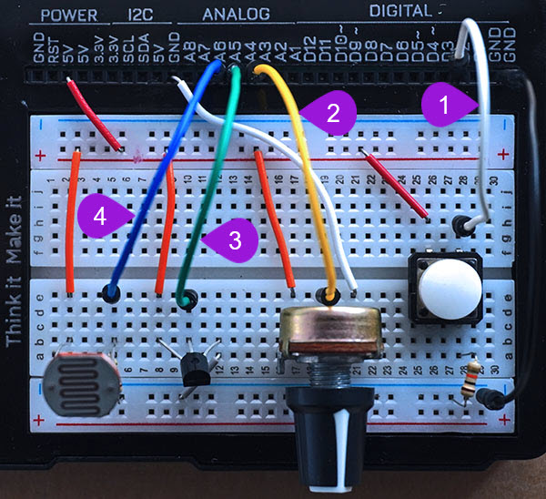
Connecting a jumper wire pushbutton: Pick a jumper wire of any color of your choice and connect it from digital pin D2 of the kit to one side of the button at breadboard pin h28 of the breadboard.
-
Connecting to the signal pin of the potentiometer: Using a jumper wire (use any color of your choice), connect one end of the jumper wire to analog pin A4 and the other end of the jumper wire to breadboard pin e19 next to the second pin of the potentiometer as shown above. The second pin is the signal pin of the potentiometer.
-
Connecting the Light sensor to analog pin: Pick another jumper wire of any colour of your choice and plug one of its' end into analog pin A5 of your UNDA.Xplora. Plug the other end of the jumper wire into breadboard pin e10 next to the second pin of the light sensor.
-
Connecting the Light sensor to analog pin: Pick a jumper wire of any colour of your choice and plug one of its' end into analog pin A6 of your UNDA.Xplora. Plug the other end of the jumper wire into breadboard pin e5 next to the second pin of the light sensor.
Run the Project
Once you are done with building the project, connect the battery to the the battery connector and then plug it to the power port of your Unda Xplora to power it on.
Follow the steps below to load up the Street Light Project.
Open Project
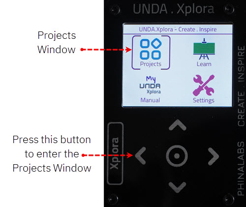
From the main window open the projects